Author: Dave Maher

CPI Unveils New Small Scale Ammonia Process

CPI has just announced significant news on some recent process technology developments, which we are happy to pass along.

CPI, one of PROCESS’ clients, has recently announced development of a new high-efficiency small-scale ammonia production process.

Natural gas is the feed material for the catalyzed process which includes innovations such as air cooling, Pressure Swing Adsorption (PSA) to remove excess carbon dioxide and nitrogen, the use of screw compressors in a relatively low-pressure synthesis section, and more.  The process has recently received a U.S. patent.  CPI is currently seeking sales opportunities and strategic partnerships globally.  Advantageous plant site targets may include remote agricultural locations with excess or stranded gas supplies, as well as regional farming cooperatives seeking to gain tighter control over their fertilizer supply and reduce shipping & storage costs.  Certain markets for ammonia derivative products (ammonium nitrate, diammonium phosphate, etc.) may also find the small modular process to their advantage.

We wish CPI continued success as they seek to commercialize this exciting technology. Follow this link to view the full article recently published in the Jan/Feb 2019 edition of Fertilizer Focus, page 49 – 51; Bridging the Gap for Small Scale Ammonia Production, by Derek Lennon.

Carbon Engineering, Ltd. Announces New Strategic Investors

Carbon Engineering Ltd. (CE) in Squamish, B.C., Canada has just announced significant news on some recent strategic investments, which we are happy to pass along.

CE has announced two major strategic investors, the first being Oxy Low Carbon Ventures, a subsidiary of Occidental Petroleum Corporation, and the second being Chevron Technology Ventures, the venture capital arm of Chevron Corporation.

These investments enable CE to accelerate commercialization of CE’s Direct Air Capture (DAC) and AIR TO FUELS™ technologies, and bring them closer to deploying large-scale commercial plants. Both Occidental and Chevron are investing into CE’s technologies and business plan, and this funding will allow CE to accelerate the use of their technologies in a way that delivers affordable, low-carbon energy, and significant emissions reductions.

CE is one of PROCESS’ valued clients whom we have served through our international projects group and wholly owned subsidiary Process Engineering International, LLC. We wish CE continued success as they seek to commercialize this exciting technology. Follow this link to view the full Press Release and/or visit the web site for Carbon Engineering, Ltd.

PROCESS Completes Basic Engineering Design of Fracking Water Treatment Demo Plant

PROCESS recently completed a project for a technology development company for a demonstration scale process designed to transform spent fracking water into clean water. Agua Dulce Technologies, LLC based in Littleton, Colorado hired PROCESS to scale up the design of a novel water treatment process from a bench top unit to a demonstration-scale pilot unit. PROCESS developed the basic engineering package for both the pretreatment and pervaporation portions of the process. Visit the web site for Agua Dulce Technologies.

Rame Sulaiman Earns Professional Engineering Registration

PROCESS is pleased to announce that Rame Sulaiman, working out of the Oak Ridge, Tennessee office, has just recently completed the requirements for and been awarded his P.E. license for the state of Tennessee. We congratulate Rame on achieving this significant accomplishment. Rame routinely leads many of our pressure relief device evaluation and sizing projects.

Rame is currently a Senior Process Engineer,a chemical engineer (M.S., Tennessee Technological University, 1995), with 22 years experience in equipment and processing systems design, startup, operation, and optimization as well as dryer, filter, and heat transfer equipment detail design and the design of process control systems.

We congratulate Rame on achieving this significant accomplishment!

Teaming Agreement with PetroDIAC in UAE

We are pleased to announce the signing of a teaming agreement between Process Engineering International, LLC (PROCESS) and PetroDIAC, an industrial consulting company with headquarters in the UAE.  Although Process Engineering International remains unbiased and independent from all other companies, the use of teaming agreements allows PROCESS to provide expert chemical engineering support to our team member’s efforts.  An alliance between PROCESS and PetroDIAC reinforces PetroDIAC’s commitment to providing the highest levels of quality services to their clients and the same high level of conduct in their business practices.

PetroDIAC is a next-generation consulting services firm founded in 1994 with offices in Houston (USA), Amsterdam (Netherlands), and Ras Al-Khaimah (UAE). PetroDIAC’s multi-disciplinary teams are dedicated to improving the profitability, efficiency and safety of Oil & Energy customers worldwide. As competent trusted advisors, our professionals apply innovative technologies and capture new opportunities for profitable growth in today’s dynamic energy market.

Process Engineering International, LLC (PROCESS) specializes in providing applied chemical process engineering skills to industry.  PROCESS serves the petroleum refining industries (upstream, midstream, and downstream), chemical production industries, petrochemical industries, metals & minerals processing, pharmaceutical industries, food and beverage industries, and all other process industries and brings a team of over 50 world class, experienced, highly-motivated chemical engineers with work histories that have significant achievements in the process engineering field and in process safety management services.  PROCESS’ consulting services range from large projects that involve complete plant process design package preparation and assistance, all the way through startup, and optimization, to small projects that only involve a few hours of consulting.

For further details, please connect with us via www.petrodiac.com and www.processengr-intl.com


PROCESS’ Mike Tanzio Featured on AIChE Website

Mr. Michael Tanzio who works for PROCESS out of our Gilbertsville, PA office, was recently invited by the American Institute of Chemical Engineers (AIChE) to share his career highlights through a new communications series called ‘Meet the Process Engineers’. Mike has enjoyed a varied and very productive employment history and was given an opportunity to comment on certain aspects of his career. If you are a chemical process engineer or are considering it as a career path, you are certain to find this article interesting. Enjoy!

https://www.aiche.org/chenected/2018/08/meet-process-engineer-michael-tanzio

ENGINEERS BEWARE: API vs ASME Relief Valve Orifice Size

Many are not aware of the major differences between the orifice sizes and discharge coefficients suggested by the API and the actual, ASME values used by the relief valve vendors. According to API-520, Part 1, the API orifice sizes and discharge coefficients are assumed values and are to be used only for the initial selection of the relief valve. They were developed to facilitate choosing a relief valve size early in a project and to ensure that the relief valve finally purchased will have a certified capacity that meets or exceeds the required relief capacity.

However, the differences in capacity between the initial choice of API orifice and the actual ASME orifice can be significant. For most projects, the actual ASME orifice can provide a much greater flowrate. When one also considers the following:

  • Conservatisms in estimating the required relief loads;
  • Calculated orifice sizes are usually between the standard, letter designated API sizes. When this occurs, the next larger orifice size is chosen resulting in the valve being oversized with just an API orifice;
  • The certified ASME discharge coefficient is derated by a factor of 0.9 resulting in another potential source of over design;

the final, purchased, relief valve can be greatly oversized.

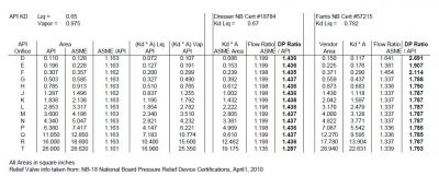
The attached table, compares just the differences between orifice designs for two relief valves versus an initial, API design. The first column is the API letter designation for the orifice, followed by the API and then the ASME orifice areas in the next two columns. The fourth column shows that, just based on orifice size, except for the “T” orifice, the ASME orifice flow area is about 16% higher than the API area.

One also needs to consider differences in valve discharge coefficients. Columns 5 and 6 show the (A * Kd) API values. Note that one should not mix and match the orifice areas and discharge coefficients. The API Kd should only be used with the API area – the same with ASME values.

Two actual relief valves are compared in the table. One is a Dresser liquid relief design with orifice areas the same as the ASME designated ones. Since many vendors have valves with areas different than ASME, the second valve is a Farris liquid relief design with orifice sizes as shown. The certified discharge coefficients are also shown for both valves.

The table shows the Farris valve to have a flowrate about 20% higher than the API valve for all sizes except “T”.  It also shows the flowrate from the Farris valve can be higher by as much as 64% for a “D” orifice. The columns next to the flow ratio for both valves show estimated pressure drop ratios which were taken just as the flow ratios squared.

PROCESS ENGINEERS BEWARE!

As shown, the actual pressure drops for the Dresser valve, using actual flow capacity can be higher than those estimated with the API flow capacity by about 44%. But, with the Farris valve, the pressure drop could be higher by a factor of 2.7!  And this does not account for conservatisms in estimating the relief load, extrapolation to larger orifice sizes, or derating of the discharge coefficient.

If not recognized early in a project, both the inlet and outlet relief valve piping could be significantly undersized as well as any downstream relief valve outlet disposal facilities (flare, scrubber, catch tank, etc.).  Issues with acoustically induced and flow induced vibration of the piping may be missed. Emissions from the disposal facilities could also be underestimated, potentially undermining any early permitting activities. All of these could result in a significantly higher capital cost for the project if not captured early.

Consideration should be made to using the ASME orifice sizes during front end engineering.

MINIMIZING PROCESS RISKS / MAXIMIZING CONFIDENCE IN YOUR CAPITAL INVESTMENTS

Overview

When executing capital projects, small or large, the ultimate objective is to produce something that works as planned, at the lowest possible cost, with the most commercially desirable attributes, and meet all applicable laws and standards.  In other words, maximize the return on investment while minimizing health and safety concerns.  To do this, it is extremely important that process risks are identified and managed in the early phases of a project to ensure that the design is robust and that project goals can be met.

Process Risks – Definition/Impact

What is a “process design risk”?  This is a risk associated with the process design that would result in the potential for a new or modified process to fail to meet the overall project objectives.   Whether the objective is to produce a new material scale up an existing process, optimize an existing process to create a better product, or simply produce a saleable product from an existing byproduct or waste stream, the decision to invest in the project assumes that a specified amount of capital investment will result in an expected amount of monetary return.   Process risks, if not identified and managed early in the project, can easily jeopardize its success and result in significant disappointment for the project owner, investors, and even product clients.

Some specific examples of process risk areas:

  • An accurate, detailed accounting of all mass and energy associated with the process has not been completed – raw materials, intermediate products, utilities, internal recycle loops, effluent waste streams, and emissions.
  • The data used as the basis for the design calculations are not robust enough to support the design (e.g. actual vapor-liquid equilibrium (VLE) data is not available, the data used for scale-up of the process did not include the correct correlations, or there was insufficient lab/pilot run-time to support the consistency of the data).
  • Sensitivity analyses are needed to define key variables that could significantly impact the detailed design of a key piece of process equipment (e.g. reflux ratio versus number of trays)
  • The unit operations required to make the product would involve multiple steps and for one or more these steps the equipment is not yet well-defined or not yet proven on a commercial scale.
  • The availability of raw materials in the quantity/quality required has not been confirmed.

These and other process design issues need to be identified and managed early in the design lifecycle of a project.  Failure to do so could result in one or more the following impacts:

  • Inability to produce a product of specified quality or at a specified throughput.
  • Generation of greater than expected effluents for discharge or treatment resulting in excessive treatment/disposal costs
  • Generation of greater than expected emissions resulting in failure to meet applicable permit limits
  • Use of more raw materials than expected resulting in higher than expected operating costs
  • A greater than expected utility requirement that not only results in higher than expected operating costs, but also requires additional capital expenditure because the existing utility infrastructure is inadequate.

All of these will result in a hit to the bottom line, not to mention wasted time, wasted resources, lost revenue, and damaged reputations.

 How to Manage and Minimize the Risks

Minimizing process design risks involves a systematic, rigorous examination of the quality of the process design.   The engineer needs to know what questions to ask, what to look for, and be able to identify all the ways that the process could potentially fail to meet the process objectives.

 Preliminary Process Design PhaseIn the early stages of a project, it is critical to perform a detailed process analysis to validate the technical feasibility of the proposed system and accurately define the major equipment and system configuration(s) that would meet the desired objectives. The information developed at this phase will provide specific insight on whether it can be done, what challenges need to be addressed for it to be successful, and how much it will really cost.

Most critical is the development of a sound Process Design Basis document as well as a detailed Heat and Material Balance (HMB) for the system.  The Process Design Basis document summarizes the raw material and product specifications, plant capacity requirements, available utilities, critical plant operating parameters that would impact the design, specific unit operations performance requirements, applicable regulatory requirements, and any other goals and/or constraints desired by the owner/operators/engineers.  Once this is in place and agreed upon by the project team, the process engineers can go to work to create, analyze, and optimize, to the extent possible, the process design.  The HMB is generated to determine the feasibility and evaluate various configurations.  It is recommended that appropriate process simulation software tools be used for this task.  The speed and accuracy of process simulation can save tremendous time and money during the preliminary design phases by allowing more efficient evaluations of various cases; e.g. plot of reflux rate versus energy usage or versus number of trays; plot of recycle rate versus yield, etc.
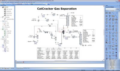
The design basis and HMB information allows the experienced process engineer to specifically define additional data needs, sensitivity analyses, technical and economic process alternative evaluations, and vendor or pilot testing needed to confidently design an optimized system.     These are tasks that should be executed prior to (or sometimes in parallel with) the development of detailed process design documents.  A precise manageable explanation of the work to be done in these tasks should be documented.

It is widely recognized that this key front-end work will have a major impact on the overall project and ultimate operation of the process. If this work is not done properly, then the project is in trouble no matter how well the subsequent detailed engineering, construction, and project management work are executed.  This information, along with a financial analysis, can be used as a sound basis for making decisions – does it makes sense to proceed? If so, what key issues need to be considered along the way?

Detailed Process Design PhaseAt this point the major process design risks have been identified and preliminary design documents have been generated – now the system components need to be integrated together to ensure the design intent can be met.  This will include such things as incorporating critical process details into the equipment specifications, developing piping and instrumentation diagrams (P&IDs) and a control scheme with consideration of all operating scenarios (startup, normal operations, shutdown, emergency shutdown).  The experienced process engineer continues to evaluate the process for how it could potentially fail and develops the best practical solutions.  After review and selection of a solution by the team, the engineer makes sure that the process design documents accurately capture these important details.
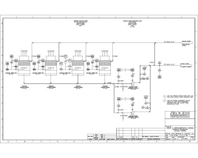
Some examples of process risks that can be mitigated during this phase include:

  • A detailed evaluation of the vent header hydraulics shows the need for a booster fan in the existing vent line to accommodate the additional load or rerouting of the vent header to another area.
  • An evaluation of the startup scenario for a specialty reactor identifies the need for an additional small heating source until the process comes to temperature or configuring the process for use of recovered heat somewhere else in the facility.
  • A review of potential upset conditions results in the need for either a small polishing filter or additional measurement devices so that permit requirements can be continuously met.

These are just a few examples of critical items that might be captured during the detailed process design phase.

Detail Engineering/Procurement/Construction Phases – Sometime during, or at the completion of the detailed process design phase, the detailed mechanical, electrical, and civil/structural design begins (detail engineering).  A well-developed detailed process design package is a critical component to the success of the detail engineering design.    Although the process engineer’ role in this phase is significantly reduced, it is critical to include them as the design progresses so that the integrity of the process design is preserved.   As companies try to keep a competitive advantage, there is great pressure to hold down costs as the civil, mechanical, electrical and instrumentation details are developed.   Removing a component that may seem unimportant can lead to the potential for off-spec product, reduced throughput, or higher operating costs.  The process risks are managed in this phase by ensuring that the experienced process engineer is present in the project reviewing drawings, equipment selection, developing operating procedures, etc.

Summary

Managing process risks through the design lifecycle of a project will greatly enhance the probability that the new or modified system will operate with the intended outcome.   The process engineer (or engineers) should have the applied design knowledge and the experience to both know how to identify the risks and design to minimize or eliminate them.  This allows the project owner can to confidently make decisions every step of the way.

2018 PHA Training Course Offered by PROCESS

PROCESS ENGINEERING ASSOCIATES, LLC is pleased to publicly offer the following 3½-day PHA training:

PROCESS HAZARD ANALYSIS (PHA) LEADER TRAINING COURSE

The purpose of the 3½ -day training course is to assist personnel at chemical plants, petrochemical plants, petroleum refineries, and manufacturing plants in becoming proficient in leading and documenting process hazard analyses (PHAs) by becoming familiar with various qualitative hazard review techniques and industry best practices for conducting and documenting PHAs.

Who should attend:  Managers and engineers responsible for conducting PHAs at chemical plants, petrochemical plants, petroleum refineries, and manufacturing plants.

Detailed instruction of the following hazard review methodologies will be included in the course:

  • Hazard and Operability (HAZOP)
  • What-If
  • Checklists
  • Failure Modes Effects Analysis (FMEA)

An introduction to Layer of Protection Analysis (LOPA) will also be included.

Select from the following course locations:

  • Houston, Texas
  • Portland, Oregon
  • Tulsa, Oklahoma
  • Philadelphia, Pennsylvania
  • Denver, Colorado
  • New Orleans, Louisiana

Please visit our website here for detailed course information and registration.  We hope to see you there!

Ventilating Your Processing Area

Overview

A safe working environment requires the evaluation and careful consideration of both general exhaust ventilation requirements and localized capture and control requirements for a chemical processing area or building.   A combination of general area exhaust systems, point source capture and control systems, and emergency release capture and control systems are required to ensure that hazards are minimized.   A systematic approach can be used to determine potential requirements for exhaust ventilation in your processing area or building.   The approach includes review of applicable standards such as the International Building Code (IBC), International Fire Code (IFC), and International Mechanical Code (IMC) as well as the National Fire Protection Association (NFPA) standards.

Approach

The systematic approach would involve the following:

  • Documenting the hazards of all chemicals handled in the area
  • Determining for each chemical the maximum quantity stored and/or used
  • Evaluating general exhaust requirements that may apply to the processing area
  • Determining if more stringent general exhaust requirements may apply to specific hazardous materials
  • Determining if localized point source capture/control requirements may apply for highly hazardous chemicals
  • Determine if there are any special requirements (e.g. compressed gases, emergency release, spill) that may apply.

Chemical Hazards

Understanding the physical and health hazards of the chemicals you handle in the area is paramount to completing a good technical review of ventilation requirements.  Therefore, material safety data sheets (MSDS’s), NFPA 704, and other sources must be used to define such things as the corrosivity, flammability (e.g. flash point and lower explosive limit LEL), and toxicity (median lethal dose (LD50) and median lethal concentration (LC50)) of the chemicals.  In addition, understanding (both qualitatively and quantitatively) whether or not a chemical can be present in the area as a vapor, gas, fume, mist or dust during any part of the operation is also important.   The basis for the hazards and any assumed concentration should be well documented.

Maximum Quantities

Specific, more stringent requirements will apply to areas where hazardous chemicals are stored and used in amounts that exceed the Maximum Allowable Quantity (MAQ) per control area (as defined in both Chapter 3 of the IBC and Chapter 50 of the IFC).   For example, the MAQ/control area for the storage of a corrosive liquid is 500 gallons.  If a corrosive liquid is stored above this quantity, more stringent ventilation requirements may apply.  The MAQ/control area for each hazardous chemical needs to be carefully defined.

General Exhaust Requirements

Regardless of the quantity of a hazardous chemical handled in the area, the codes require that general exhaust systems be provided, maintained and operated to make sure any fumes/mists/vapors/dusts that may present a physical and/or health hazard are discharged outdoors with no chance of re-entering through the building ventilation system.   Some examples of general exhaust requirements provided in Chapters 4 and 5 of the IMC include the following:

  • If natural ventilation is used, ensure a minimum of 4 percent of the floor area is openable to the outdoors.
  • Provide adequate makeup air and maintain a neutral or negative air pressure throughout the area
  • Locate inlets to the exhaust systems at areas of heaviest contamination.

Other physical design requirements are provided in these Chapters.

General Exhaust Requirements for Hazardous Materials

Additional requirements exist in areas where hazardous materials are stored or dispensed and used in amounts greater than the MAQ per control area.  Using the same example above, if a corrosive liquid is stored, used or dispensed in a quantity greater than 500 gallons, the mechanical exhaust system for the area will also have to meet additional requirements including:

  • Design capacity for 1 cfm/ft21 cfm/ft2 of floor area over storage or use area.
  • Operate continuously.
  • Equip with a manual shutoff switch, labeled and located outside the room adjacent to the access door.
  • If the vapor density is greater than air, the exhaust vents should be located no more than 12 inches off the floor (for chemicals lighter than air, exhaust from a point within 12 inches of the highest point of the room).
  • Design to provide air movement across all portions of the floor (no dead spaces) and allow no recirculation of exhausted air back into the room.

Localized Exhaust Requirements

Ventilation may need to be expanded to include localized point source capture and exhaust if more hazardous conditions can potentially exist, some of which include the following:

  • A hazardous chemical with an NFPA health hazard rating of 3 or 4 is used in amounts exceeding the MAQ per control area.
  • A “corrosive” material is dispensed and/or used in amounts exceeding the MAQ per control area
  • A highly-toxic or toxic liquid is dispensed and/or used in amounts exceeding the MAQ per control area

As an example, if a Chlorine solution (corrosive, NFPA 4 rating) is pumped to a tank that has an open vent, a localized point source capture and exhaust system may need to be designed around that vent.

Hazardous Materials-Specific Requirements

Once general exhaust and localized exhaust requirements are defined, additional requirements should be identified for specific hazardous materials conditions; for instance, the potential for a spill or accidental release of a highly toxic chemical.   It is important to define the potential worst-case spill or accidental release scenarios and to estimate the concentration of harmful fumes that could be generated and emitted.   The mechanical exhaust system may need to be equipped with a scrubber system to process these vapors (if the concentration is potentially harmful).  There are other requirements for specific hazardous materials, such as those for storage or use of highly-toxic and toxic compressed gases, or flammable and combustible liquids, which would be considered, as relevant.   These are well-defined in the standards referenced.

Conclusion

A good ventilation review requires a thorough understanding of the chemicals in the area, how they are stored and used, and their potential hazards.  With that information, a systematic technical review can be implemented to summarize the ventilation requirements for your processing area.