Overview
When executing capital projects, small or large, the ultimate objective is to produce something that works as planned, at the lowest possible cost, with the most commercially desirable attributes, and meet all applicable laws and standards. In other words, maximize the return on investment while minimizing health and safety concerns. To do this, it is extremely important that process risks are identified and managed in the early phases of a project to ensure that the design is robust and that project goals can be met.
Process Risks – Definition/Impact
What is a “process design risk”? This is a risk associated with the process design that would result in the potential for a new or modified process to fail to meet the overall project objectives. Whether the objective is to produce a new material scale up an existing process, optimize an existing process to create a better product, or simply produce a saleable product from an existing byproduct or waste stream, the decision to invest in the project assumes that a specified amount of capital investment will result in an expected amount of monetary return. Process risks, if not identified and managed early in the project, can easily jeopardize its success and result in significant disappointment for the project owner, investors, and even product clients.
Some specific examples of process risk areas:
- An accurate, detailed accounting of all mass and energy associated with the process has not been completed – raw materials, intermediate products, utilities, internal recycle loops, effluent waste streams, and emissions.
- The data used as the basis for the design calculations are not robust enough to support the design (e.g. actual vapor-liquid equilibrium (VLE) data is not available, the data used for scale-up of the process did not include the correct correlations, or there was insufficient lab/pilot run-time to support the consistency of the data).
- Sensitivity analyses are needed to define key variables that could significantly impact the detailed design of a key piece of process equipment (e.g. reflux ratio versus number of trays)
- The unit operations required to make the product would involve multiple steps and for one or more these steps the equipment is not yet well-defined or not yet proven on a commercial scale.
- The availability of raw materials in the quantity/quality required has not been confirmed.
These and other process design issues need to be identified and managed early in the design lifecycle of a project. Failure to do so could result in one or more the following impacts:
- Inability to produce a product of specified quality or at a specified throughput.
- Generation of greater than expected effluents for discharge or treatment resulting in excessive treatment/disposal costs
- Generation of greater than expected emissions resulting in failure to meet applicable permit limits
- Use of more raw materials than expected resulting in higher than expected operating costs
- A greater than expected utility requirement that not only results in higher than expected operating costs, but also requires additional capital expenditure because the existing utility infrastructure is inadequate.
All of these will result in a hit to the bottom line, not to mention wasted time, wasted resources, lost revenue, and damaged reputations.
How to Manage and Minimize the Risks
Minimizing process design risks involves a systematic, rigorous examination of the quality of the process design. The engineer needs to know what questions to ask, what to look for, and be able to identify all the ways that the process could potentially fail to meet the process objectives.
Preliminary Process Design Phase – In the early stages of a project, it is critical to perform a detailed process analysis to validate the technical feasibility of the proposed system and accurately define the major equipment and system configuration(s) that would meet the desired objectives. The information developed at this phase will provide specific insight on whether it can be done, what challenges need to be addressed for it to be successful, and how much it will really cost.
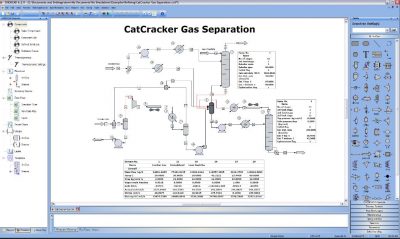
Most critical is the development of a sound Process Design Basis document as well as a detailed Heat and Material Balance (HMB) for the system. The Process Design Basis document summarizes the raw material and product specifications, plant capacity requirements, available utilities, critical plant operating parameters that would impact the design, specific unit operations performance requirements, applicable regulatory requirements, and any other goals and/or constraints desired by the owner/operators/engineers. Once this is in place and agreed upon by the project team, the process engineers can go to work to create, analyze, and optimize, to the extent possible, the process design. The HMB is generated to determine the feasibility and evaluate various configurations. It is recommended that appropriate process simulation software tools be used for this task. The speed and accuracy of process simulation can save tremendous time and money during the preliminary design phases by allowing more efficient evaluations of various cases; e.g. plot of reflux rate versus energy usage or versus number of trays; plot of recycle rate versus yield, etc.
The design basis and HMB information allows the experienced process engineer to specifically define additional data needs, sensitivity analyses, technical and economic process alternative evaluations, and vendor or pilot testing needed to confidently design an optimized system. These are tasks that should be executed prior to (or sometimes in parallel with) the development of detailed process design documents. A precise manageable explanation of the work to be done in these tasks should be documented.
It is widely recognized that this key front-end work will have a major impact on the overall project and ultimate operation of the process. If this work is not done properly, then the project is in trouble no matter how well the subsequent detailed engineering, construction, and project management work are executed. This information, along with a financial analysis, can be used as a sound basis for making decisions – does it makes sense to proceed? If so, what key issues need to be considered along the way?
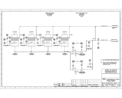
Detailed Process Design Phase – At this point the major process design risks have been identified and preliminary design documents have been generated – now the system components need to be integrated together to ensure the design intent can be met. This will include such things as incorporating critical process details into the equipment specifications, developing piping and instrumentation diagrams (P&IDs) and a control scheme with consideration of all operating scenarios (startup, normal operations, shutdown, emergency shutdown). The experienced process engineer continues to evaluate the process for how it could potentially fail and develops the best practical solutions. After review and selection of a solution by the team, the engineer makes sure that the process design documents accurately capture these important details.
 Some examples of process risks that can be mitigated during this phase include:
- A detailed evaluation of the vent header hydraulics shows the need for a booster fan in the existing vent line to accommodate the additional load or rerouting of the vent header to another area.
- An evaluation of the startup scenario for a specialty reactor identifies the need for an additional small heating source until the process comes to temperature or configuring the process for use of recovered heat somewhere else in the facility.
- A review of potential upset conditions results in the need for either a small polishing filter or additional measurement devices so that permit requirements can be continuously met.
These are just a few examples of critical items that might be captured during the detailed process design phase.
Detail Engineering/Procurement/Construction Phases – Sometime during, or at the completion of the detailed process design phase, the detailed mechanical, electrical, and civil/structural design begins (detail engineering). A well-developed detailed process design package is a critical component to the success of the detail engineering design. Although the process engineer’ role in this phase is significantly reduced, it is critical to include them as the design progresses so that the integrity of the process design is preserved. As companies try to keep a competitive advantage, there is great pressure to hold down costs as the civil, mechanical, electrical and instrumentation details are developed. Removing a component that may seem unimportant can lead to the potential for off-spec product, reduced throughput, or higher operating costs. The process risks are managed in this phase by ensuring that the experienced process engineer is present in the project reviewing drawings, equipment selection, developing operating procedures, etc.
Summary
Managing process risks through the design lifecycle of a project will greatly enhance the probability that the new or modified system will operate with the intended outcome. The process engineer (or engineers) should have the applied design knowledge and the experience to both know how to identify the risks and design to minimize or eliminate them. This allows the project owner can to confidently make decisions every step of the way.
 plants, petrochemical plants, petroleum refineries, and manufacturing plants in becoming proficient in leading and documenting process hazard analyses (PHAs) by becoming familiar with various qualitative hazard review techniques and industry best practices for conducting and documenting PHAs.