Category: Blog

2018 PHA Training Course Offered by PROCESS

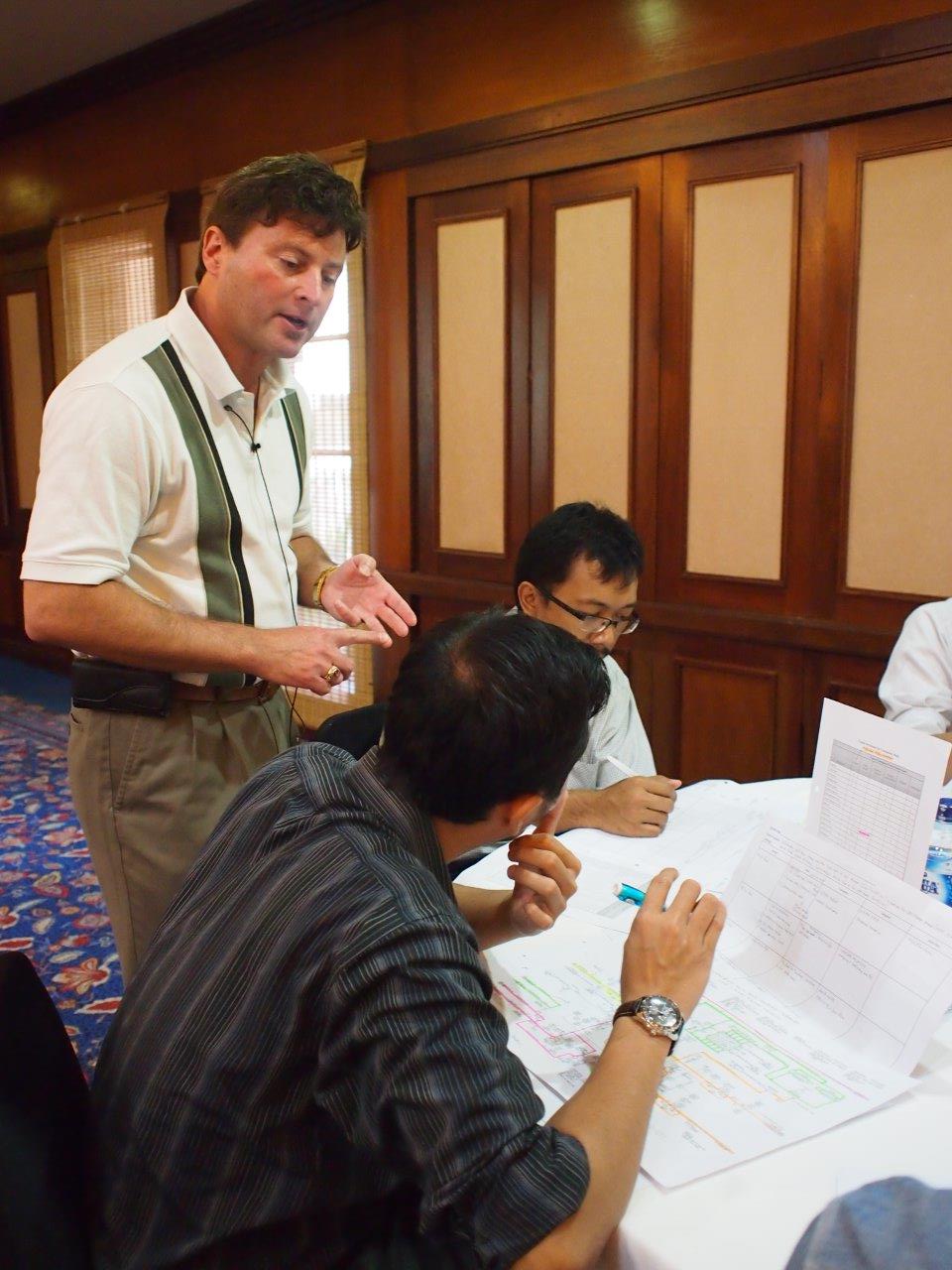
PROCESS ENGINEERING ASSOCIATES, LLC is pleased to publicly offer the following 3½-day PHA training:

PROCESS HAZARD ANALYSIS (PHA) LEADER TRAINING COURSE

The purpose of the 3½ -day training course is to assist personnel at chemical plants, petrochemical plants, petroleum refineries, and manufacturing plants in becoming proficient in leading and documenting process hazard analyses (PHAs) by becoming familiar with various qualitative hazard review techniques and industry best practices for conducting and documenting PHAs.
Who should attend:  Managers and engineers responsible for conducting PHAs at chemical plants, petrochemical plants, petroleum refineries, and manufacturing plants.

Detailed instruction of the following hazard review methodologies will be included in the course:

  • Hazard and Operability (HAZOP)
  • What-If
  • Checklists
  • Failure Modes Effects Analysis (FMEA)

An introduction to Layer of Protection Analysis (LOPA) will also be included.

Select from the following course locations:

  • Houston, Texas
  • Portland, Oregon
  • Tulsa, Oklahoma
  • Philadelphia, Pennsylvania
  • Denver, Colorado
  • New Orleans, Louisiana

Please visit our website here for detailed course information and registration.  We hope to see you there!

Ventilating Your Processing Area

Overview

A safe working environment requires the evaluation and careful consideration of both general exhaust ventilation requirements and localized capture and control requirements for a chemical processing area or building.   A combination of general area exhaust systems, point source capture and control systems, and emergency release capture and control systems are required to ensure that hazards are minimized.   A systematic approach can be used to determine potential requirements for exhaust ventilation in your processing area or building.   The approach includes review of applicable standards such as the International Building Code (IBC), International Fire Code (IFC), and International Mechanical Code (IMC) as well as the National Fire Protection Association (NFPA) standards.

Approach

The systematic approach would involve the following:

  • Documenting the hazards of all chemicals handled in the area
  • Determining for each chemical the maximum quantity stored and/or used
  • Evaluating general exhaust requirements that may apply to the processing area
  • Determining if more stringent general exhaust requirements may apply to specific hazardous materials
  • Determining if localized point source capture/control requirements may apply for highly hazardous chemicals
  • Determine if there are any special requirements (e.g. compressed gases, emergency release, spill) that may apply.

Chemical Hazards

Understanding the physical and health hazards of the chemicals you handle in the area is paramount to completing a good technical review of ventilation requirements.  Therefore, material safety data sheets (MSDS’s), NFPA 704, and other sources must be used to define such things as the corrosivity, flammability (e.g. flash point and lower explosive limit LEL), and toxicity (median lethal dose (LD50) and median lethal concentration (LC50)) of the chemicals.  In addition, understanding (both qualitatively and quantitatively) whether or not a chemical can be present in the area as a vapor, gas, fume, mist or dust during any part of the operation is also important.   The basis for the hazards and any assumed concentration should be well documented.

Maximum Quantities

Specific, more stringent requirements will apply to areas where hazardous chemicals are stored and used in amounts that exceed the Maximum Allowable Quantity (MAQ) per control area (as defined in both Chapter 3 of the IBC and Chapter 50 of the IFC).   For example, the MAQ/control area for the storage of a corrosive liquid is 500 gallons.  If a corrosive liquid is stored above this quantity, more stringent ventilation requirements may apply.  The MAQ/control area for each hazardous chemical needs to be carefully defined.

General Exhaust Requirements

Regardless of the quantity of a hazardous chemical handled in the area, the codes require that general exhaust systems be provided, maintained and operated to make sure any fumes/mists/vapors/dusts that may present a physical and/or health hazard are discharged outdoors with no chance of re-entering through the building ventilation system.   Some examples of general exhaust requirements provided in Chapters 4 and 5 of the IMC include the following:

  • If natural ventilation is used, ensure a minimum of 4 percent of the floor area is openable to the outdoors.
  • Provide adequate makeup air and maintain a neutral or negative air pressure throughout the area
  • Locate inlets to the exhaust systems at areas of heaviest contamination.

Other physical design requirements are provided in these Chapters.

General Exhaust Requirements for Hazardous Materials

Additional requirements exist in areas where hazardous materials are stored or dispensed and used in amounts greater than the MAQ per control area.  Using the same example above, if a corrosive liquid is stored, used or dispensed in a quantity greater than 500 gallons, the mechanical exhaust system for the area will also have to meet additional requirements including:

  • Design capacity for 1 cfm/ft21 cfm/ft2 of floor area over storage or use area.
  • Operate continuously.
  • Equip with a manual shutoff switch, labeled and located outside the room adjacent to the access door.
  • If the vapor density is greater than air, the exhaust vents should be located no more than 12 inches off the floor (for chemicals lighter than air, exhaust from a point within 12 inches of the highest point of the room).
  • Design to provide air movement across all portions of the floor (no dead spaces) and allow no recirculation of exhausted air back into the room.

Localized Exhaust Requirements

Ventilation may need to be expanded to include localized point source capture and exhaust if more hazardous conditions can potentially exist, some of which include the following:

  • A hazardous chemical with an NFPA health hazard rating of 3 or 4 is used in amounts exceeding the MAQ per control area.
  • A “corrosive” material is dispensed and/or used in amounts exceeding the MAQ per control area
  • A highly-toxic or toxic liquid is dispensed and/or used in amounts exceeding the MAQ per control area

As an example, if a Chlorine solution (corrosive, NFPA 4 rating) is pumped to a tank that has an open vent, a localized point source capture and exhaust system may need to be designed around that vent.

Hazardous Materials-Specific Requirements

Once general exhaust and localized exhaust requirements are defined, additional requirements should be identified for specific hazardous materials conditions; for instance, the potential for a spill or accidental release of a highly toxic chemical.   It is important to define the potential worst-case spill or accidental release scenarios and to estimate the concentration of harmful fumes that could be generated and emitted.   The mechanical exhaust system may need to be equipped with a scrubber system to process these vapors (if the concentration is potentially harmful).  There are other requirements for specific hazardous materials, such as those for storage or use of highly-toxic and toxic compressed gases, or flammable and combustible liquids, which would be considered, as relevant.   These are well-defined in the standards referenced.

Conclusion

A good ventilation review requires a thorough understanding of the chemicals in the area, how they are stored and used, and their potential hazards.  With that information, a systematic technical review can be implemented to summarize the ventilation requirements for your processing area.

How Many Pressure Relief Devices (PSDs) Do you have venting to Atmosphere? Are They Safe?

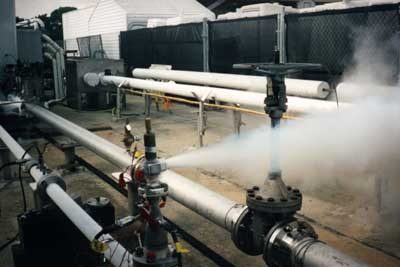
Determining if the atmospheric release from a pressure relief device (PSD) is safe is good engineering practice and a requirement defined by OSHA and ASME.   Relief devices that are not connected to a closed relief system (flare header, knock out pot, etc.) should have tailpipes to direct the relieving stream to a safe area.  An engineer can use readily available tools to preliminarily screen most atmospheric releases to determine if a more detailed quantitative evaluation is needed to generate a relief design guideline.  The combination of preliminary screening, semi-quantitative evaluation and more detailed quantitative evaluation can be used to streamline the overall review process.

Screening

Initial screening of each valve should be performed to categorize the level of risk.  This involves a review of the existing PSD sizing calculations and existing hazards evaluation reports/recommendations to classify each device into one of the following categories based on the nature of the fluid discharged:

  • Relief devices that simply need to be piped so that discharge does not have the potential to impinge personnel in its path or inhibit an operator from performing a function in an emergency. Examples of this are low pressure steam releases or thermal cooling water reliefs.
  • Relief devices that may have a slightly higher level of safety concern and will require some qualitative evaluation to define a specific relief guideline. Examples of this are a release of an asphyxiant or a saturated vapor that may condense.
  • Relief devices that will require more detailed quantitative analysis to generate a relief guideline. Examples of this are flammable vapors, toxic vapors, vapors heavier than air, and vapors that may cause an offsite odor issue.
  • Relief devices that are special cases. For example, a relief device that has been sized for vapor release but may have situations that could release a flammable liquid, a 2-phase mixture, or solids.  These will require special design considerations.   Releases of liquids or solids to the atmosphere are not acceptable and will require special design (i.e. containment or safety instrumentation to eliminate a credible release scenario).

The screening step determines which valves should be carried further into a quantitative evaluation so that a relief guideline can be established.   First and foremost, a conservative approach should be taken in the screening step to minimize the possibility that unsafe atmospheric PSD discharge could escape detection and not be flagged for further, more detailed, quantitative evaluation by the engineering team.

 Semi-Quantitative Analysis

Preliminary calculations are performed to compare data to key process parameters that allow for a more detailed definition of the potential risk associated with the release and determine if a more detailed quantitative evaluation (such as dispersion modeling) should be performed.   The key variables include the following:

  • Adequate mixing – API STD 521 6thAPI STD 521 6th edition 5.8 provides guidelines to determine if a relief device discharge to atmosphere is acceptable based on the mixing effects at the discharge. To semi-quantitatively determine if a release is acceptable, the following criteria must be met:
    1. Exit velocity should be greater than 100 ft/sec. Studies have shown that the hazard of flammable concentrations existing below the point of discharge is negligible as long as the discharge velocity is sufficiently high.  The evaluation should be done at various valve capacities (e.g. 25%, 50% and 100% of the rating) since there is a potential that the valve discharge rate may be lower than the actual rated capacity of the valve.
    2. Vapor MW should be less than 80
    3. Relief temperature should be at or below the atmospheric temperature.

If any of these criteria are not met, it should be assumed that adequate mixing may not exist and a potential for an unacceptable concentration at ground-level may be present.

  • Vapor density – if the vapor density is heavier than air, the vapor cloud may migrate to ground level and pose a hazard. Additional analysis is needed to determine if the ground-level concentration could be flammable or toxic.
  • Vapor Reynolds Number (Nre) – if the vapor Nre  > 1.54 * 104* (ρj/ρ∞) , per API STD 521 6th edition § 5.8.2.2

ρj = density of gas at the vent outlet

ρ∞ = density of the air

then the jet momentum forces of release are usually dominant.  Else, the jet entrainment of air is limited, and flammable mixtures can possibly occur at grade or downwind. Additional analysis is needed to determine if the ground-level concentration could be flammable or toxic.

Note: The above equation may not be valid for jet velocity < 40 ft/s (12m/s) or jet-wind velocity ratio < 10.

  • Potential for mist formation – the potential for mist formation to occur exists if the relief stream dew point is above the minimum ambient temperature at the site. A design that includes a knockout drum or scrubber should be installed in relief lines to separate and remove liquid droplets from the discharge.
  • Maximum ground-level concentration (flammability and toxicity) – a preliminary screening calculation to determine the maximum estimated concentration at grade (Cmax) can be done to determine if further dispersion modeling should be performed. This information can be compared to the lower explosive limit (LEL) for flammable vapors (is Cmax greater than 25% of the LEL?) and to applicable exposure limits for toxic vapors (is Cmax close to the IDLH or TLV for that compound?).  For example, a highly flammable material released that is above the LEL at the release point should be evaluated for the potential to reach >25% of the LEL at grade.

Note:  One reference that provides a screening equation for Cmax is “Consequence Analysis of Atmospheric Discharge from Pressure Relief Devices, Qualitative and Quantitative Safety Screening” (Burgess, John P.E., Smith, Dustin P.E., Smith & Burgess Process Safety Consulting).

  • Asphyxiant hazard – if an asphyxiant is discharged and the vapor release is heavier than air, additional evaluation may be needed, depending on the location of the relief device, to determine if there is a potential for buildup or re-entrainment of the vapors in occupied spaces.

Again, a conservative approach should be taken in the semi-quantitative analysis.  Borderline acceptability of the above parameters should be considered for further modeling to ensure that the potential risk is accurately defined.

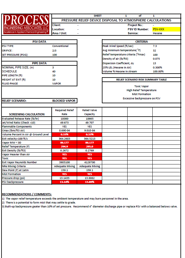
An example summary of the screening and preliminary semi-quantitative analysis is presented in the below summary table for a PSV releasing hexane.

As a result of this semi-quantitative analysis, each valve can be classified into a specific risk category.     Depending on the risks, you can either (1) define an atmospheric relief guideline for the valve so that the PSD design can be completed or (2) determine that a more detailed quantitative analysis (e.g. dispersion modeling) should be performed to better understand the potential risk.

Detailed Quantitative Analysis

Results of the screening and preliminary semi-quantitative analysis may indicate that additional analysis (such as detailed dispersion modeling) is required to more specifically define the potential release pattern and level of risk associated with the vapor release such that a specific guideline can be established for the design of the tailpipe.

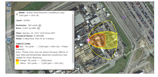
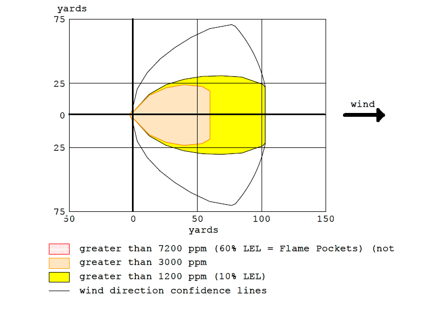
One method that is widely used to model these types of releases is ALOHA®.  ALOHA® is a hazards modeling program that can define potential threat zones for chemical releases and can be used for flammable vapors, toxic vapors, BLEVEs (boiling liquid expansion vapor explosions), jet fires, pool fires, and vapor cloud explosions.  This software package is from the CAMEO® Software Suite and can be downloaded for free at https://www.epa.gov/cameo.

In the example above, ALOHA® was used to define the potential threat zones for the release of hexane from the PSD.

Using MARPLOT®, also a software program in the CAMEO Software Suite, the ALOHA threat zone estimate can be displayed on the map of the facility to graphically display the potential impact and better prepare for the chemical release.

Conclusion

An engineer can use readily available tools to screen most atmospheric release PSDs to define a specific relief guideline for that PSD.  The evaluation should include both a qualitative screening and, as needed, more detailed quantitative methods to streamline the review and develop documentation that proves the discharge configuration is safe.

Helping You With NFPA 652/654

The initial issue of NFPA 652, Standard on the Fundamentals of Combustible Dust, was issued in September 2015.  OSHA uses the NFPA standards as the basis for enforcement in managing combustible dust hazards.  Are you on track for compliance with the standards?

The new standard provides the basic principles of and requirements for identifying and managing the fire and explosion hazards of combustible dusts and particulate solids.  Of notable interest is Chapter 7 which introduces the Dust Hazard Analysis (DHA). The DHA is different from other forms of risk assessments such as a Process Hazard Analysis (PHA) as it has narrower requirements of specifically assessing dust hazards.  The requirement is retroactive and the new standard does not allow the absence of previous incidents as a basis for deeming a particulate to not be combustible or explosible.

PROCESS can provide clients with a review of their existing particulate solid handling systems to develop a plan for bringing them into compliance with the NFPA 652/654 standards.  Such services often involve the following tasks:

A. Site Visit

  • Visit each facility to review the existing unit operations, gather technical data, meet with Operations personnel, and review system operating procedures and Process Hazards Analyses (PHA).

B. Evaluation Basis Preparation / Hazards Assessment

  • Detail the basis of design/evaluation for the equipment/system handling the particulate solid
  • Determine if there is sufficient information to document that the particulate solid is a combustible dust and if the particular equipment involved poses a dust explosion hazard. If applicable, define additional laboratory or field testing requirements to complete this effort (e.g. physical properties, flows, concentrations, etc.).

C. Dust Hazards technical evaluation

  • Conduct a systematic review of existing dust hazards.  The review will consider all phases of operation; Normal, Startup, Shutdown.
  • Work with the client to rank the degree of hazards for each area so that a strategic plan can be developed for more detailed qualitative evaluations.

D. Dust Hazards Risk assessment

  • For selected areas, facilitate and participate in a detailed Risk Assessment (similar to a PHA) to qualitatively determine the scope of the hazard and define the necessary steps and/or modifications required to comply with the NFPA standards.
  • Preparation of a formal risk assessment report that includes an explanation of methodology used, a description of a basis for the recommendations, and an appendix that includes a Risk Assessment Summary Table and/or worksheets.

E. Additional services

  • Identification of Technical Alternatives for System Upgrades with a list of design, physical installation, and operational modifications that could be implemented to meet the new/updated standards.
  • Capital Cost Estimate for proposed modifications for planning purposes.

Technical Information Supporting a Standard Technology Licensing Project

A successful technology licensing project will typically pass through three distinct phases from start to finish:

·   Phase I: Non-Confidential Disclosure

·   Phase II: Confidential Disclosure

·   Phase III: Technology Delivery

The technical information developed during the first two phases facilitates a technology licensing sale by supporting a compelling story regarding why the licensed technology offers the best solution for that potential client’s unique needs while at the same time protecting the licensor’s proprietary information. After the technology licensing sale is made, the licensor must deliver that technology to the client clearly and effectively so that they can execute the project in an efficient manner, and can startup and operate the new production unit successfully.

I.  Non-Confidential Disclosure

The primary objective of this initial phase is to introduce the licensed technology with its key features, and to draw a potential client into a discussion regarding the intended project. Some of the information provided during this initial phase may be present on the technology licensor’s web site, such as:

· Introduction (technology overview, licensor description and background)

· Key advantages of the technology versus alternatives/competition (whatever they might be: investment, operating cost, other)

· Technology description (Block Flow Diagram, high-level Process Description)

· Technology flexibility (as appropriate: raw material flexibility, product flexibility)

Discussions with the client during this initial phase should also highlight other important features of the licensed technology offering, such as:

· Technology delivery (documentation, training)

· Technical support (during detailed design, during startup, following startup)

Another key objective of this initial phase is to gather critical data from the client regarding the project so that the information provided during Phase II can be tailored to specific needs, such as capacity, product mix, raw material slate, etc. The Non-Confidential phase of the project concludes when the licensor and potential client enter into a Non-Disclosure Agreement.


II.  Confidential Disclosure

After the Non-Disclosure Agreement is finalized, the licensor can provide the client with a detailed Confidential Disclosure package that is customized to the specific project. The objective is to provide high level economic data regarding the application of the licensed technology to the project (such as expected investment and operating costs), and to include sufficient detailed supporting information so that the client may verify the claims independently (but not detailed enough for them to construct a similar process). Information provided at this stage consists of documentation such as:

· Process Description

· Process Flow Diagrams

· Sized Equipment List

· Overall raw material and utility consumption rates

· High-level effluent and waste generation rates

· Typical plot plan and elevation drawings.

This phase of the project typically include a tour(s) of the licensor’s reference plant and/or pilot facilities where the technology was developed. Such visits not only help the client gain confidence in the robustness of the licensed technology, but also helps to foster informal discussions between the licensor and client technical teams that are critical to a successful technology license sale.

During this phase of the project, the licensor may present a value proposition for the licensed technology, detailing the specific technical advantages that the licensed technology brings to the client versus the alternatives/competition and quantifying the value of each advantage in economic terms, such as investment and/or operating cost savings.

As this phase of the project, much of the discussion will become focused on developing the Technology License Agreement, which is primarily a commercial document. The License Agreement also includes several key technical components such as:

· Production capacity, product mix and raw material slate

· Technology Delivery contents and schedule

· Performance warranty parameters and test run procedures.

The Confidential Disclosure phase concludes when the parties enter into a Technology Licensing Agreement.

III.  Technology Delivery

During the Technology Delivery phase of the project the licensor conveys to the client all of the technical information that is needed to successfully build and operate the new production unit, consisting of documentation, training, and technical support.

Soon after the Technology Licensing Agreement is signed, the licensor and client will conduct a design conference during which all of the design data previously exchanged is confirmed. Once the design basis is confirmed and agreed upon, the licensor can begin preparing the technical documentation accordingly.

A Technology Manual is normally assembled and transmitted to the client which includes all of the key R&D reports that document the fundamental basis for the licensed technology.

A Process Design Package (PDP) is transmitted that includes the licensor information that the client will require to build their new production unit in accordance with the licensed technology, including:

· Detailed Process Description

· Major and Minor Equipment Specifications

· Control Systems Data Sheets

· Control Logic Diagrams and Logic Descriptions

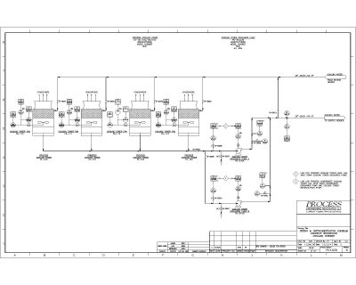
· Piping and Instrumentation Diagrams

· Line and Equipment Lists

· Valve and Piping Specifications

· Process Flow Diagrams with Heat and Material Balances

· Detailed Utility Consumption and Waste Generation Lists

· Supplemental Design Information.

The Technology License Agreement will specify that the client must build their production unit in complete and strict accordance with the PDP for the performance warranties to be valid. The License Agreement will also typically state that the client is ultimately responsible for adapting the design to the local site conditions, for ensuring that the production unit complies with all applicable local codes and standards, and for the safe design and operation of the process. Thus, the level of content in the PDP must be carefully calibrated to convey all mandatory licensor requirements while leaving the client maximum flexibility to satisfy their obligations.

Example for a typical PDP:

· The PDP will specify inside battery limits process facilities only. The client should be responsible for the design of outside battery limits and support facilities.

· The PDP will include process design level of information only. The client should be responsible for detailed design.

 · The PDP will reflect the codes and standards that apply within the licensor’s country of origin. The client should be responsible for the application of local codes and standards.

· The PDP will be based on a typical production process layout. The client should be responsible for adapting the design to their actual site configuration.

· The client should be solely responsible for the safe design of the production unit, including all pressure relief devices. The licensor should identify the sizing scenarios that must be checked, but will not assume liability for the final relief device sizes.

Once the PDP has been issued, the licensor conducts a process design orientation training session to present the PDP to the client, and to aid in the transition of the project to the client team and detailed design contractor. This training is typically attended by the client’s technical staff and senior operating supervisors, along with the key design leads from the detailed design contractor.

During detailed design, the client and detailed design contractor will most often have questions regarding the PDP for clarification. The licensor must commit to respond to such inquiries in a timely manner to help their work continue smoothly.

The licensor will usually also provide the client a set of operating procedures for their operations staff to use as a guide while they develop the operating procedures for their specific process.

Once the client has identified the staff who will operate their new production unit, the licensor should plan to provide detailed and extensive operations training for these personnel, typically at the licensor’s reference unit or pilot facilities. Such training should address startup, shutdown, normal operation and emergency scenarios so that the client’s staff will be able to perform their duties successfully.

When construction of the client’s new production unit is nearing mechanical completion, the licensor will dispatch a startup team to the operating site to assist the client’s operating staff in commissioning and startup activities. The startup team will remain at site though the successful completion of all warranty test runs specified in the Technology License Agreement.

After startup and for a period specified in the License Agreement, the licensor may agree to meet with the client periodically for review of their operational results, and to convey to the client any technology improvements that may have been recently developed.

How PROCESS Can Help

PROCESS’ business model does not allow ownership of any licensed technology and therefore, PROCESS can assist clients who are developing a new technology by preparing technical documentation required in all three phases of the licensing process. PROCESS can:

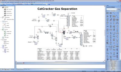
· Develop a simulation model of the new technology.

· Assist the licensor with refining and optimizing the design.

· Develop all the necessary process design documents. The simulation model will also aid in expediting the preparation of independent design documents that need to be tailored to each specific client’s needs.

· Assist with commissioning and startup.

PROCESS can also assist clients who are interested in purchasing a licensed process technology in several ways:

· Identify existing technologies that might be suitable for the desired application.

· Perform technical and techno/economic screening studies of the available technologies to assist during the evaluation and selection phase.

· Independently validate the technical and economic claims of the selected technology provider such as; expected investment, operating costs, raw material requirements etc.

· Develop OSB process design, utility upgrade information, PSV sizing requirements and similar information that may not be included in the technology package.

· Guide clients through the entire process as an Owner’s Engineer Process Consultant.

· Assist with process oversite during detailed design and construction.

Note: PROCESS’ engineers are almost never named as co-inventors on patents. In the event we are named as co-inventors, we, as an engineering and not a technology company, will sign our rights over to our client. All work performed by PROCESS and intellectual property developed by PROCESS is paid for and owned by our clients.