
Written by: Christopher J. Muntean, P.E.
Senior Process Engineer at Process Engineering Associates
March 18, 2024
Background
Various assessments are conducted to promote the safe and reliable operation of process plants in the industry. Some of these assessments include: Hazard and Operability (HAZOP), Process Hazard Analysis (PHA), and Layer of Protection Analysis (LOPA).
During these workshops, a group of cross-functional individuals (often engineers and safety professionals), work together to identify the major hazards within process units. Once these hazards are identified, the team develops effective preventive measures. The identification of such hazards serves as a crucial step in mitigating potential safety and environmental incidents.
Estimating theoretical consequences during a hazards assessment is often done qualitatively. While value can be provided in this manner, it must be noted that other tools exist for a process engineer to support these events in a more quantitative approach. Namely, detailed dispersion modeling. Dispersion modeling can provide numerical results as well as visual graphical representation of the identified consequences. The results from such modeling can be overlaid on plant plot plans or even Google Earth imagery during PHA/HAZOP/LOPA workshops to provide further clarity in evaluating hazardous scenarios. Team members can then further enhance their understanding of an incident by visualizing the impact of the release to the three-dimensional surroundings, such as equipment or buildings.
PROCESS has experience using such modeling tools to support our clients during these assessments.
Practical Examples of Dispersion Modeling
A detailed dispersion modeling effort using well designed software generally allows for a wide range of equipment and consequence scenarios to be evaluated to support these hazard assessments. PROCESS has utilized industry accepted dispersion/modeling tools (i.e. Chemcad, ALOHA, DNV PHAST, etc.) to support clients with their hazard assessments. Some specific examples include: (1) pressure relief device (PRD) atmospheric release dispersion modeling, (2) flare thermal radiation and/or flameout modeling, and (3) In-building chemical releases. Such examples are further discussed as following:
1. Pressure Relief Device Modeling
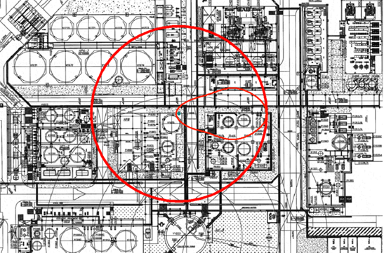
Relief devices that are not connected to a closed relief system (flare header, knock out pot, etc.) should have the tail-pipes directed to a safe relief location. Determining if the atmospheric release is truly to a safe location is a requirement defined by OSHA and ASME. This practice is also recommended in API 520, Part I. Dispersion modeling can provide results to determine relief discharge piping height and location requirements to comply with these codes and standards. PROCESS has conducted various dispersion modeling assessments for clients who wish to understand the potential impacts of a toxic chemical release from a safety valve to the atmosphere. PROCESS recently conducted dispersion modeling on a large anhydrous ammonia storage tank with 3 PRDs (atmospheric relief). The model indicated that during a fire scenario, the atmospheric relief could potentially result in toxic conditions to nearby structures or locations in the plant. Our client used the data from the modeling to support their safety plan.
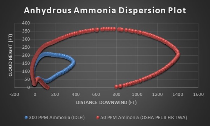
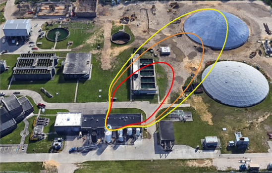
In addition, atmospheric PRD dispersion results can be overlaid on satellite imagery to provide further insight when evaluating hazardous scenarios.
2. Flare Thermal Radiation or Flameout Modeling
Flares provide a certain amount of thermal radiation to nearby pipe racks, buildings, people, and process equipment. This level of radiation changes depending on flaring amount, duration, and certain environmental factors such as wind or time of day. Dispersion modeling can support a project by allowing such radiation effects to be plotted over various radiation levels. This may prove to be beneficial should new equipment, buildings, or pipe racks need to be installed or re-routed.
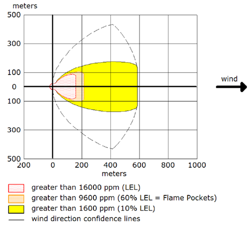
Additionally, during a flare flameout scenario, a large flammable cloud may persist for quite some distance. Dispersion modeling can support the effects of such a scenario. PROCESS has recently conducted a similar exercise for a client who was considering a hypothetical large hydrocarbon release occurring while the pilots were distinguished on the flare. Dispersion modeling for that exercise revealed where flammable regions may exist on the site plot plan.
3. Inside Building Releases
Inside building releases can be modeled. For example, an indoor leak in a lab may build up a large concentration prior to being released outside. The outdoor release and effects can be modeled, along with possible explosion effects.
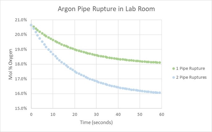
In addition, indoor releases can be modeled considering asphyxiation, by showing oxygen depletion over-time at certain portions in a room or building. This may be valuable if there is a need to consider a nitrogen or argon line rupture in an occupied room. PROCESS has conducted such an exercise for a client with a lab environment where an argon pipe rupture was considered. The room oxygen concentration was estimated over time as the leak event unfolded. This helped the client determine safety planning if such an incident should unfold.
Other Potential Uses for Dispersion Modeling
While a few practical examples were listed, dispersion modeling may also prove to add value for various other incidents or planning efforts. These include, but are not limited to:
- Emergency Response Planning
- Incident investigation
- Spill and Loss of Containment Events
- Pipeline Leaks
- Facility Citing and Occupied Building Risk Assessments
Conclusion
Whether the end user is in oil and gas, petrochemical, pharmaceutical, the public sector, or a storage facility; accurate dispersion modeling can be an important tool to help ensure safety is not compromised during the design and operation of a facility.
A detailed dispersion study can provide numerical and visual representation of potential consequences identified in hazard assessments (e.g. PRD relief, flare upset condition, inbuilding rupture releases, etc.). Such results allow safety professionals to develop strategies to prevent future re-occurrences, develop best practices, and make informed decisions to emergency response plans and overall safety measures.
References
1. American Society of Mechanical Engineers, ‘Boiler and Pressure Vessel Code, Section VIII, Division I, Subsection A, Part UG-135(f) (2009).
2. Occupational Safety and Health Administration (OSHA), 1910 Subpart H, Hazardous Materials, Dispensing Devices, 1910.110(h)
3. American Petroleum Institute, API 520, Part I, 10th Ed. (2020), Section 4 – Pressure Relief Devices