Author: Dave Maher

2018 PHA Leader Training Courses Offered in U.S.

PROCESS ENGINEERING ASSOCIATES, LLC is pleased to publicly offer the following 3½-day PHA training course: PROCESS HAZARD ANALYSIS (PHA) LEADER TRAINING COURSE

The purpose of the 3½ -day training course is to assist personnel at chemical plants, petrochemical plants, petroleum refineries, and manufacturing plants in becoming proficient in leading and documenting process hazard analyses (PHAs) by becoming familiar with various qualitative hazard review techniques and industry best practices for conducting and documenting PHAs.

Who should attend:  Managers and engineers responsible for conducting PHAs at chemical plants, petrochemical plants, petroleum refineries, and manufacturing plants.

Detailed instruction of the following hazard review methodologies will be included in the course:

  • Hazard and Operability (HAZOP)
  • What-If
  • Checklists
  • Failure Modes Effects Analysis (FMEA).

An introduction to Layer of Protection Analysis (LOPA) will also be included.

How Many Pressure Relief Devices (PSDs) Do you have venting to Atmosphere? Are They Safe?

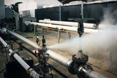
Determining if the atmospheric release from a pressure relief device (PSD) is safe is good engineering practice and a requirement defined by OSHA and ASME.   Relief devices that are not connected to a closed relief system (flare header, knock out pot, etc.) should have tailpipes to direct the relieving stream to a safe area.  An engineer can use readily available tools to preliminarily screen most atmospheric releases to determine if a more detailed quantitative evaluation is needed to generate a relief design guideline.  The combination of preliminary screening, semi-quantitative evaluation and more detailed quantitative evaluation can be used to streamline the overall review process.

Screening

Initial screening of each valve should be performed to categorize the level of risk.  This involves a review of the existing PSD sizing calculations and existing hazards evaluation reports/recommendations to classify each device into one of the following categories based on the nature of the fluid discharged:

  • Relief devices that simply need to be piped so that discharge does not have the potential to impinge personnel in its path or inhibit an operator from performing a function in an emergency. Examples of this are low pressure steam releases or thermal cooling water reliefs.
  • Relief devices that may have a slightly higher level of safety concern and will require some qualitative evaluation to define a specific relief guideline. Examples of this are a release of an asphyxiant or a saturated vapor that may condense.
  • Relief devices that will require more detailed quantitative analysis to generate a relief guideline. Examples of this are flammable vapors, toxic vapors, vapors heavier than air, and vapors that may cause an offsite odor issue.
  • Relief devices that are special cases. For example, a relief device that has been sized for vapor release but may have situations that could release a flammable liquid, a 2-phase mixture, or solids.  These will require special design considerations.   Releases of liquids or solids to the atmosphere are not acceptable and will require special design (i.e. containment or safety instrumentation to eliminate a credible release scenario).

The screening step determines which valves should be carried further into a quantitative evaluation so that a relief guideline can be established.   First and foremost, a conservative approach should be taken in the screening step to minimize the possibility that unsafe atmospheric PSD discharge could escape detection and not be flagged for further, more detailed, quantitative evaluation by the engineering team.

 Semi-Quantitative Analysis

Preliminary calculations are performed to compare data to key process parameters that allow for a more detailed definition of the potential risk associated with the release and determine if a more detailed quantitative evaluation (such as dispersion modeling) should be performed.   The key variables include the following:

  • Adequate mixing – API STD 521 6thAPI STD 521 6th edition 5.8 provides guidelines to determine if a relief device discharge to atmosphere is acceptable based on the mixing effects at the discharge. To semi-quantitatively determine if a release is acceptable, the following criteria must be met:
    1. Exit velocity should be greater than 100 ft/sec. Studies have shown that the hazard of flammable concentrations existing below the point of discharge is negligible as long as the discharge velocity is sufficiently high.  The evaluation should be done at various valve capacities (e.g. 25%, 50% and 100% of the rating) since there is a potential that the valve discharge rate may be lower than the actual rated capacity of the valve.
    2. Vapor MW should be less than 80
    3. Relief temperature should be at or below the atmospheric temperature.

If any of these criteria are not met, it should be assumed that adequate mixing may not exist and a potential for an unacceptable concentration at ground-level may be present.

  • Vapor density – if the vapor density is heavier than air, the vapor cloud may migrate to ground level and pose a hazard. Additional analysis is needed to determine if the ground-level concentration could be flammable or toxic.
  • Vapor Reynolds Number (Nre) – if the vapor Nre  > 1.54 * 104* (ρj/ρ∞) , per API STD 521 6th edition § 5.8.2.2

ρj = density of gas at the vent outlet

ρ∞ = density of the air

then the jet momentum forces of release are usually dominant.  Else, the jet entrainment of air is limited, and flammable mixtures can possibly occur at grade or downwind. Additional analysis is needed to determine if the ground-level concentration could be flammable or toxic.

Note: The above equation may not be valid for jet velocity < 40 ft/s (12m/s) or jet-wind velocity ratio < 10.

  • Potential for mist formation – the potential for mist formation to occur exists if the relief stream dew point is above the minimum ambient temperature at the site. A design that includes a knockout drum or scrubber should be installed in relief lines to separate and remove liquid droplets from the discharge.
  • Maximum ground-level concentration (flammability and toxicity) – a preliminary screening calculation to determine the maximum estimated concentration at grade (Cmax) can be done to determine if further dispersion modeling should be performed. This information can be compared to the lower explosive limit (LEL) for flammable vapors (is Cmax greater than 25% of the LEL?) and to applicable exposure limits for toxic vapors (is Cmax close to the IDLH or TLV for that compound?).  For example, a highly flammable material released that is above the LEL at the release point should be evaluated for the potential to reach >25% of the LEL at grade.

Note:  One reference that provides a screening equation for Cmax is “Consequence Analysis of Atmospheric Discharge from Pressure Relief Devices, Qualitative and Quantitative Safety Screening” (Burgess, John P.E., Smith, Dustin P.E., Smith & Burgess Process Safety Consulting).

  • Asphyxiant hazard – if an asphyxiant is discharged and the vapor release is heavier than air, additional evaluation may be needed, depending on the location of the relief device, to determine if there is a potential for buildup or re-entrainment of the vapors in occupied spaces.

Again, a conservative approach should be taken in the semi-quantitative analysis.  Borderline acceptability of the above parameters should be considered for further modeling to ensure that the potential risk is accurately defined.

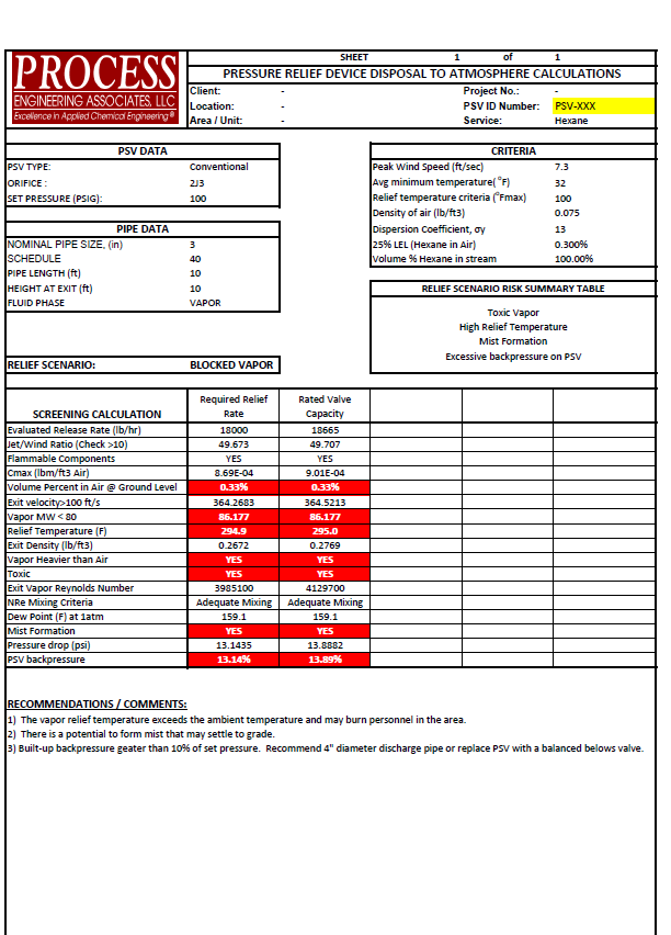
An example summary of the screening and preliminary semi-quantitative analysis is presented in the below summary table for a PSV releasing hexane.

As a result of this semi-quantitative analysis, each valve can be classified into a specific risk category.     Depending on the risks, you can either (1) define an atmospheric relief guideline for the valve so that the PSD design can be completed or (2) determine that a more detailed quantitative analysis (e.g. dispersion modeling) should be performed to better understand the potential risk.

Detailed Quantitative Analysis

Results of the screening and preliminary semi-quantitative analysis may indicate that additional analysis (such as detailed dispersion modeling) is required to more specifically define the potential release pattern and level of risk associated with the vapor release such that a specific guideline can be established for the design of the tailpipe.

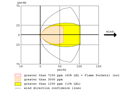
One method that is widely used to model these types of releases is ALOHA®.  ALOHA® is a hazards modeling program that can define potential threat zones for chemical releases and can be used for flammable vapors, toxic vapors, BLEVEs (boiling liquid expansion vapor explosions), jet fires, pool fires, and vapor cloud explosions.  This software package is from the CAMEO® Software Suite and can be downloaded for free at https://www.epa.gov/cameo.

In the example above, ALOHA® was used to define the potential threat zones for the release of hexane from the PSD.

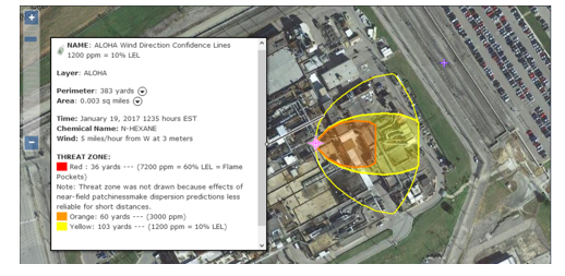
Using MARPLOT®, also a software program in the CAMEO Software Suite, the ALOHA threat zone estimate can be displayed on the map of the facility to graphically display the potential impact and better prepare for the chemical release.

Conclusion

An engineer can use readily available tools to screen most atmospheric release PSDs to define a specific relief guideline for that PSD.  The evaluation should include both a qualitative screening and, as needed, more detailed quantitative methods to streamline the review and develop documentation that proves the discharge configuration is safe.

Helping You With NFPA 652/654

The initial issue of NFPA 652, Standard on the Fundamentals of Combustible Dust, was issued in September 2015.  OSHA uses the NFPA standards as the basis for enforcement in managing combustible dust hazards.  Are you on track for compliance with the standards?

The new standard provides the basic principles of and requirements for identifying and managing the fire and explosion hazards of combustible dusts and particulate solids.  Of notable interest is Chapter 7 which introduces the Dust Hazard Analysis (DHA). The DHA is different from other forms of risk assessments such as a Process Hazard Analysis (PHA) as it has narrower requirements of specifically assessing dust hazards.  The requirement is retroactive and the new standard does not allow the absence of previous incidents as a basis for deeming a particulate to not be combustible or explosible.

PROCESS can provide clients with a review of their existing particulate solid handling systems to develop a plan for bringing them into compliance with the NFPA 652/654 standards.  Such services often involve the following tasks:

A. Site Visit

  • Visit each facility to review the existing unit operations, gather technical data, meet with Operations personnel, and review system operating procedures and Process Hazards Analyses (PHA).

B. Evaluation Basis Preparation / Hazards Assessment

  • Detail the basis of design/evaluation for the equipment/system handling the particulate solid
  • Determine if there is sufficient information to document that the particulate solid is a combustible dust and if the particular equipment involved poses a dust explosion hazard. If applicable, define additional laboratory or field testing requirements to complete this effort (e.g. physical properties, flows, concentrations, etc.).

C. Dust Hazards technical evaluation

  • Conduct a systematic review of existing dust hazards.  The review will consider all phases of operation; Normal, Startup, Shutdown.
  • Work with the client to rank the degree of hazards for each area so that a strategic plan can be developed for more detailed qualitative evaluations.

D. Dust Hazards Risk assessment

  • For selected areas, facilitate and participate in a detailed Risk Assessment (similar to a PHA) to qualitatively determine the scope of the hazard and define the necessary steps and/or modifications required to comply with the NFPA standards.
  • Preparation of a formal risk assessment report that includes an explanation of methodology used, a description of a basis for the recommendations, and an appendix that includes a Risk Assessment Summary Table and/or worksheets.

E. Additional services

  • Identification of Technical Alternatives for System Upgrades with a list of design, physical installation, and operational modifications that could be implemented to meet the new/updated standards.
  • Capital Cost Estimate for proposed modifications for planning purposes.

Technical Information Supporting a Standard Technology Licensing Project

A successful technology licensing project will typically pass through three distinct phases from start to finish:

·   Phase I: Non-Confidential Disclosure

·   Phase II: Confidential Disclosure

·   Phase III: Technology Delivery

The technical information developed during the first two phases facilitates a technology licensing sale by supporting a compelling story regarding why the licensed technology offers the best solution for that potential client’s unique needs while at the same time protecting the licensor’s proprietary information. After the technology licensing sale is made, the licensor must deliver that technology to the client clearly and effectively so that they can execute the project in an efficient manner, and can startup and operate the new production unit successfully.

I.  Non-Confidential Disclosure

The primary objective of this initial phase is to introduce the licensed technology with its key features, and to draw a potential client into a discussion regarding the intended project. Some of the information provided during this initial phase may be present on the technology licensor’s web site, such as:

· Introduction (technology overview, licensor description and background)

· Key advantages of the technology versus alternatives/competition (whatever they might be: investment, operating cost, other)

· Technology description (Block Flow Diagram, high-level Process Description)

· Technology flexibility (as appropriate: raw material flexibility, product flexibility)

Discussions with the client during this initial phase should also highlight other important features of the licensed technology offering, such as:

· Technology delivery (documentation, training)

· Technical support (during detailed design, during startup, following startup)

Another key objective of this initial phase is to gather critical data from the client regarding the project so that the information provided during Phase II can be tailored to specific needs, such as capacity, product mix, raw material slate, etc. The Non-Confidential phase of the project concludes when the licensor and potential client enter into a Non-Disclosure Agreement.


II.  Confidential Disclosure

After the Non-Disclosure Agreement is finalized, the licensor can provide the client with a detailed Confidential Disclosure package that is customized to the specific project. The objective is to provide high level economic data regarding the application of the licensed technology to the project (such as expected investment and operating costs), and to include sufficient detailed supporting information so that the client may verify the claims independently (but not detailed enough for them to construct a similar process). Information provided at this stage consists of documentation such as:

· Process Description

· Process Flow Diagrams

· Sized Equipment List

· Overall raw material and utility consumption rates

· High-level effluent and waste generation rates

· Typical plot plan and elevation drawings.

This phase of the project typically include a tour(s) of the licensor’s reference plant and/or pilot facilities where the technology was developed. Such visits not only help the client gain confidence in the robustness of the licensed technology, but also helps to foster informal discussions between the licensor and client technical teams that are critical to a successful technology license sale.

During this phase of the project, the licensor may present a value proposition for the licensed technology, detailing the specific technical advantages that the licensed technology brings to the client versus the alternatives/competition and quantifying the value of each advantage in economic terms, such as investment and/or operating cost savings.

As this phase of the project, much of the discussion will become focused on developing the Technology License Agreement, which is primarily a commercial document. The License Agreement also includes several key technical components such as:

· Production capacity, product mix and raw material slate

· Technology Delivery contents and schedule

· Performance warranty parameters and test run procedures.

The Confidential Disclosure phase concludes when the parties enter into a Technology Licensing Agreement.

III.  Technology Delivery

During the Technology Delivery phase of the project the licensor conveys to the client all of the technical information that is needed to successfully build and operate the new production unit, consisting of documentation, training, and technical support.

Soon after the Technology Licensing Agreement is signed, the licensor and client will conduct a design conference during which all of the design data previously exchanged is confirmed. Once the design basis is confirmed and agreed upon, the licensor can begin preparing the technical documentation accordingly.

A Technology Manual is normally assembled and transmitted to the client which includes all of the key R&D reports that document the fundamental basis for the licensed technology.

A Process Design Package (PDP) is transmitted that includes the licensor information that the client will require to build their new production unit in accordance with the licensed technology, including:

· Detailed Process Description

· Major and Minor Equipment Specifications

· Control Systems Data Sheets

· Control Logic Diagrams and Logic Descriptions

· Piping and Instrumentation Diagrams

· Line and Equipment Lists

· Valve and Piping Specifications

· Process Flow Diagrams with Heat and Material Balances

· Detailed Utility Consumption and Waste Generation Lists

· Supplemental Design Information.

The Technology License Agreement will specify that the client must build their production unit in complete and strict accordance with the PDP for the performance warranties to be valid. The License Agreement will also typically state that the client is ultimately responsible for adapting the design to the local site conditions, for ensuring that the production unit complies with all applicable local codes and standards, and for the safe design and operation of the process. Thus, the level of content in the PDP must be carefully calibrated to convey all mandatory licensor requirements while leaving the client maximum flexibility to satisfy their obligations.

Example for a typical PDP:

· The PDP will specify inside battery limits process facilities only. The client should be responsible for the design of outside battery limits and support facilities.

· The PDP will include process design level of information only. The client should be responsible for detailed design.

 · The PDP will reflect the codes and standards that apply within the licensor’s country of origin. The client should be responsible for the application of local codes and standards.

· The PDP will be based on a typical production process layout. The client should be responsible for adapting the design to their actual site configuration.

· The client should be solely responsible for the safe design of the production unit, including all pressure relief devices. The licensor should identify the sizing scenarios that must be checked, but will not assume liability for the final relief device sizes.

Once the PDP has been issued, the licensor conducts a process design orientation training session to present the PDP to the client, and to aid in the transition of the project to the client team and detailed design contractor. This training is typically attended by the client’s technical staff and senior operating supervisors, along with the key design leads from the detailed design contractor.

During detailed design, the client and detailed design contractor will most often have questions regarding the PDP for clarification. The licensor must commit to respond to such inquiries in a timely manner to help their work continue smoothly.

The licensor will usually also provide the client a set of operating procedures for their operations staff to use as a guide while they develop the operating procedures for their specific process.

Once the client has identified the staff who will operate their new production unit, the licensor should plan to provide detailed and extensive operations training for these personnel, typically at the licensor’s reference unit or pilot facilities. Such training should address startup, shutdown, normal operation and emergency scenarios so that the client’s staff will be able to perform their duties successfully.

When construction of the client’s new production unit is nearing mechanical completion, the licensor will dispatch a startup team to the operating site to assist the client’s operating staff in commissioning and startup activities. The startup team will remain at site though the successful completion of all warranty test runs specified in the Technology License Agreement.

After startup and for a period specified in the License Agreement, the licensor may agree to meet with the client periodically for review of their operational results, and to convey to the client any technology improvements that may have been recently developed.

How PROCESS Can Help

PROCESS’ business model does not allow ownership of any licensed technology and therefore, PROCESS can assist clients who are developing a new technology by preparing technical documentation required in all three phases of the licensing process. PROCESS can:

· Develop a simulation model of the new technology.

· Assist the licensor with refining and optimizing the design.

· Develop all the necessary process design documents. The simulation model will also aid in expediting the preparation of independent design documents that need to be tailored to each specific client’s needs.

· Assist with commissioning and startup.

PROCESS can also assist clients who are interested in purchasing a licensed process technology in several ways:

· Identify existing technologies that might be suitable for the desired application.

· Perform technical and techno/economic screening studies of the available technologies to assist during the evaluation and selection phase.

· Independently validate the technical and economic claims of the selected technology provider such as; expected investment, operating costs, raw material requirements etc.

· Develop OSB process design, utility upgrade information, PSV sizing requirements and similar information that may not be included in the technology package.

· Guide clients through the entire process as an Owner’s Engineer Process Consultant.

· Assist with process oversite during detailed design and construction.

Note: PROCESS’ engineers are almost never named as co-inventors on patents. In the event we are named as co-inventors, we, as an engineering and not a technology company, will sign our rights over to our client. All work performed by PROCESS and intellectual property developed by PROCESS is paid for and owned by our clients.

PROCESS Opens New Office in Salt Lake City, Utah

October 24, 2016 – PROCESS announces the official opening of a new engineering regional office in Salt Lake City, UT. This office is being opened to better serve clients in the region in markets such as minerals processing, refining, etc. The office will be managed by Mr. Mike Sessions, P.E.

Rocky Mountain Regional Branch
1011 East Murray Holladay Road, Suite 102

Salt Lake City, UT 84117

(801) 824-8444

PROCESS Increases Refining Process Engineering Capabilities

PROCESS has added to its excellent staff a very high caliber process engineer who has significant petroleum refining design and operations experience. We are pleased to welcome Mr. Michael Tanzio to our Gilbertsville, PA office team. Mike brings a great deal of experience to our team that our refining clients will benefit from for years to come. A summary of his qualifications is provided below.

Mr. Michael (Mike) Tanzio, Chief Process Engineer, a chemical engineer (M.S., Purdue University, 1977) with 42 years experience in process research & development and design including process modeling/simulation, process development, process safety analysis, piloting, troubleshooting and debottlenecking of a variety of processes including oil refining, gas processing, petrochemicals, biomass processing, energy and other chemical production processes, as well as providing process engineering leadership to many engineering / construction capital projects involving the conceptual, FEED, detailed design, and construction phases. Select refinery experience includes the following locations, projects, and duties:

Sonangol Lobito Refinery, Lobito, Angola – New Amine Regeneration unit, Sour Water Stripper, Sulfur Recovery unit and Saturated Gas Plant for a grassroots 200,00 BPD refinery. Work scope development and man-hour estimates for detailed engineering for multiple refinery units (FEED).

Suncor Montreal Refinery, Montreal Quebec, Canada – Delayed Coker LPG olefins hydrotreater (Process design package).

TOTAL Lindsey Oil Refinery, Immingham, UK – New diesel / heating oil hydrotreater including a new hydrodesulfurization unit, hydrogen plant, sulfur recovery unit, sour water stripper, and amine regeneration unit and utility systems upgrade (FEED).

KNPC Shuaiba Refinery, Shuaiba, Kuwait – Amine (MEA) treating facilities for treating sour gas (FEED).

Sunoco Eagle Point Refinery, Westville, NJ (Shutdown) – Low sulfur gasoline hydrotreater (Detailed / Construction). Out-of-service gasoline hydrotreater revamp (Conceptual). Cumene unit revamp expansion (FEED / Detailed).

Sunoco Point Breeze Refinery, Philadelphia, PA (Philadelphia Energy Solutions) – Low sulfur gasoline hydrotreater (Detailed / Construction). FCC debottlenecking revamp including the FCC feed preheat train, wet gas compressor, main fractionator, gas plant and existing gas caustic treating system. (Conceptual). New FCC flue gas economizer (Conceptual). Propane Terminal Upgrade (Conceptual / FEED). Hydrogen Purification membrane unit (Conceptual). Flare header replacement / Relief valve adequacy (Conceptual / FEED / Detailed). Absorption tower performance (Conceptual). TAME unit study (Conceptual). Deisobutanizer modifications (Conceptual). Crude unit relief study (Conceptual).

Chevron / Sunoco Girard Point Refinery, Philadelphia, PA (Philadelphia Energy Solutions) – MTBE offsites revamp including marine barge unloading, component storage, gasoline blending, gasoline storage, and oxygenate removal unit (FEED / Detailed). Butane isomerization offsites including feed preparation, feed storage, and utilities (FEED)Refinery steam production economics (Study).

Sunoco Toledo Refinery, Toledo, Ohio (PBF Energy) – Crude unit / FCC debottlenecking revamp (Conceptual). Low sulfur gasoline hydrotreater (Detailed / Construction).

Sunoco Marcus Hook Refinery, Marcus Hook, PA (Shutdown, now an “Industrial Complex”) – Flare header and process vent study (Conceptual).

Mobil / Valero Paulsboro Refinery, Paulsboro, NJ (PBF Energy) – CHD relief valve study (Conceptual). ZSM-5 catalyst commercial plant test (Research & Development). FCC unit performance monitoring (Tech service). HF Alkylation unit debottleneck revamp including FCC gas plant (FEED / Detailed). Refinery relief load study (Conceptual).

Conoco Bayway Refinery, Linden, NJ (Phillips66) – Flare header and process vent study (Conceptual).

Star Enterprise Delaware City Refinery, Delaware City, DE (PBF Energy) – Refinery strategies for reformulated gasoline production (Conceptual). Propane storage vapor recovery (Conceptual). Benzene railcar facility (FEED / Detailed).

Marathon Garyville Refinery, Garyville, LA – HF Alkylation unit equipment corrosion (Study). HF acid truck unloading overpressure protection (Conceptual). HF Alkylation unit relief load mitigation strategy (Study).

Citgo Paulsboro Asphalt Refinery, Paulsboro, NJ (Axeon Specialty Products) – Crude and Vacuum unit relief valve modifications (FEED / Detailed). Caustic pipeline pig station (FEED). Boiler feedwater and service water systems debottleneck revamp (Conceptual). P&ID updates for OSHA 1910 (Tech service).

BP Trainer Refinery, Trainer, PA (Monroe Energy/Delta Airlines) – Light ends rail facility (FEED / Detailed). Catalytic Reformer benzene reduction & chloride treating (Conceptual / FEED / Detailed). Vacuum tower vacuum system and hot well revamp (Conceptual).

Process Simulator Skills:

    • Simci (Pro/II, VisualFlare)
    • Hyprotech (Hysys, Flarenet)
    • Aspen (AspenPlus, Icarus Process Evaluator)
    • BR&E (ProMax)
    • CHEMCAD.

Mike Sessions, P.E. Becomes Company Partner

Effective January 1, 2015, Mike Sessions has been made a partner (Member) of PROCESS.  Since joining our company in early 2011, Mike has been the driving force behind the establishment and growth of PROCESS’ Gulf Coast Regional office as its Business Unit Manager.  He has spent countless hours doing what has been the hallmark of achievement at PROCESS – using only his raw talent and determination, building something out of nothing.  Now fully in tune with the philosophies and practices of PROCESS, the existing partners believe it is time to welcome Mike’s input to company management on an equal basis.  Please join us in congratulating Mike on his new role at PROCESS.

New Partnership Targets Turn-Key Projects

August 2014 – Walbridge Process Engineering & Construction (WPE&C) is a newly formed full-service EPC firm combining the process engineering capabilities of Process Engineering Associates, LLC (PROCESS) with construction expert Walbridge (http://www.walbridge.com/). The company is based in Greenville, S.C. and offers process engineering, detail engineering (via subcontract), and construction services to customers in the chemical process industry, as well as the food and beverage, pharmaceutical, specialty chemical, and oil and gas industries. WPE&C has global reach and specializes in providing tailored solutions to industrial process clients looking for a single source project partner.

Does this mean PROCESS is now offering detail engineering services – NO, NEVER! We note that while process engineering, design management, and construction services will be offered directly by the new firm, detail design services will be subcontracted. Therefore, it does mean that some of our trusted engineering company clients may have an opportunity to participate as team members on turn-key projects that neither they nor PROCESS had opportunities for in the past. PROCESS will remain an independent process engineering company able to provide services in a non-competitive manner to many engineering company clients. WPE&C will pursue project opportunities where clients require turn-key EPC services.

Detail engineering services on all WPE&C projects are provided through key subcontracted design partners selected to best suit each specific opportunity, based on the detail company’s experience, the project needs, and geography. This unique approach allows the EPC team to be closely tailored to the particular requirements of each assignment, providing the best match of resources to every project. We believe the intentional strategic use of outside detail engineering group subcontractors provides an unsurpassed opportunity to customize a turn-key capable EPC project team for each specific project. This unique combination of two very specialized groups at opposite ends of the project spectrum (process engineering and construction) combined with the plug-and-play approach to detail engineering is a first of its kind to the best of our knowledge. Think about it – you’re hiring a deep, stable, senior level process group with no pressures to feed work to a large detail design team, you’re hiring a detail design team that has been hand selected for your specific project (not a one size fits all approach), and you’re hiring a seasoned construction group who is an industry leader in safety and lean construction practices and has a “lessons learned” database comprised of nearly 4,500 ‘don’t forget’ experiences from past projects.

What does PROCESS get out of this partnership? Only the potential to work and get paid for the process engineering services we provide as part of a turn-key project team, nothing else…no commissions, no percentage of profits, nothing else. We refuse to receive payment for anything other than providing our process engineering services so that our independence and unbiased technical objectivity is never at risk or in question. That is just one way we will continue to bring value to so many different types of clients.

Visit the webpage of Walbridge Process Engineering & Construction (WPE&C) to learn more.

Alternative Natural Rubber Pilot-Plant Project for Ohio State University Makes News

Process Engineering Associates, LLC (PROCESS) was contracted by a major U.S. University research group to assist in the development of a pilot scale process to produce an alternative source of refined natural rubber extracted from the roots of a Russian dandelion plant.  The goal of the project is to lessen U.S. dependence on natural rubber imported mainly from Southeastern Asia which is used in tire manufacturing.  While pilot scale work had been conducted during the 1940s as part of the war effort, the researchers sought to recreate and improve the process at the lab scale.  PROCESS used a combination of this information to design certain key unit operations needing further lab work, as well as generate simulations, preliminary material and energy balances, and an order of magnitude cost estimate for a pilot and commercial scale facility.  PROCESS worked closely with the researchers to develop and optimize a unique counter-current extraction process to separate the rubber from the plant roots.  PROCESS then developed a comprehensive process design package (HMBs, PFDs, P&IDs, equipment specs., etc.) and subsequently assisted the client during the startup phase. Read the article in the Ohio Country Journal. More information on this project can be Viewed Here.

InvestorIntel Invterview: Hop Boyd on the Real Advantage of Having the Right Chemical Processing Engineer on the Job

Toronto, Ontario–(Newsfile Corp. – April 10, 2014) – Hop Boyd Jr., Chief Manager, Process Engineering Associates LLC (PROCESS) speaks to Tracy Weslosky, Editor-in-Chief and Publisher of InvestorIntel. Hop has been a chemical engineer for many years and he describes his job, in jest, as a “highly educated plumber”. Of course, PROCESS does much more than that. It offers process engineering services – as opposed to electrical, mechanical or structural – from design and to safety services, relying on its over 50 highly qualified, full-time chemical engineers. As a further analogy, Hop describes the typical scenario of a prospective client approaching PROCESS to shift from the small scale production of a given chemical to an industrial one. In other words Hop and his team will help the client by designing and developing a process on an industrial scale “that will manufacture methyl-ethyl-death or whatever it is in this person’ dreams to manufacture.”

The crucial issue for InvestorIntel, however, is what PROCESS can do for rare earth companies. Hop promptly says that PROCESS will not help them get the mineral out of the ground: “but when you get something out of the ground, you have to separate it or purify it, or even possibly convert it into another form. And that’s where we come in, designing, troubleshooting, and helping with processes to do that.” What should happen if the rare earth companies choose the wrong process engineering solutions? Hop offers a personal account to explain what can go wrong. Indeed, the story relates to the ‘genesis’ of Process Engineering itself. Hop “was working as a process engineer for another company at a major chemical company client site and we were working on a separate process when an engineer said: come to the back, where there was a brand new process sitting there; it was beautiful… But, the engineer told me that it got 50% of the production that it was supposed to deliver.” In other words the design of that chemical process was “messed up”, because they didn’t hire the proper chemical process engineering team from the very beginning.

PROCESS is a company made up exclusively by chemical engineers. As such PROCESS is uniquely qualified to evaluate the viability of a given project, offering as unbiased an answer as possible. That is because “other engineering companies have chemical as well as mechanical, civil, electrical engineering and in most cases they make their money mostly from these latter disciplines; therefore, there is a tendency… or a subtle pressure to have a project move forward, that the answer from the beginning of the chemical process design, the engineer says, yes, this makes sense, it needs to move forward,” influencing the other disciplines. Hop explains that PROCESS does not have a “dog in the fight” as to whether or not a project goes forward. The risk, then, is that the comprehensive engineering companies are under more pressure to give a project a favorable evaluation in order to see a project proceed, whereas PROCESS is solely focused on evaluating the chemical aspects.